
Analysis of CNC turned and milled parts

Machining Process Analysis of Typical cnc turned and milled parts
Abstract: The CNC machining process arrangement of the combined turning and milling parts involves considering the processing sequence and clamping scheme to ensure the machining accuracy and dimensional tolerance of the parts. Taking a connecting ring as an example, the part drawing is analyzed, the machining content is determined, the machining route is arranged, and a clamping scheme is designed based on the structure. The selection of tools and cutting parameters is also analyzed.
Keywords: CNC turning and milling; CNC machining process; connecting ring; CNC turned and milled parts;CNC turning milling parts; CNC turning and milling process.
The machining of combined turning and milling parts is not a simple combination of turning and milling processes; it requires careful consideration of processing sequence and clamping schemes to ensure precision. Using a component from an injection molding machine, a connecting ring, as an example, this study analyzes the CNC machining process for combined turning and milling. The part has an overall disc shape, featuring an outer circle, inner hole, end face, counter bored hole, threaded hole, U-shaped open slot, and a group of stepped holes in the center of the disc. The disc's end face has a circular hole and a set of U-shaped open slots. This is a typical combined turning and milling part, with a requirement for high precision in the machining of the inner hole and moderate precision for the circular holes and U-shaped slots on the end face of the part.
Pattern Analysis
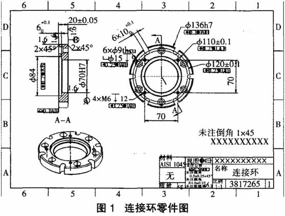
Table 1 Machining content
| Content | Demand |
|---|---|
| $135h7 mm excircle | Diameter 135(0/-0.04)mm |
| $70H7 mm hole | Diameter 70(+0.03/0)mm |
| $84 mm hole | Diameter $84(+0.25/-0.25)mm. Depth is 6(+0.1/0)mm |
| 6 u-shape groove | The groove width is 10(+0.1/0)mm, the groove depth is all through, and the center circle diameter is $120(+0.1/-0.1mm) |
| 6 Counterbore | Countersunk hole diameter 15 (+/- 0.25-0.25) mm, depth of 9 (+/-0.25-0.25) mm, hole diameter 9 (+/- 0.25-0.25) mm, depth all through |
| 4 M6 threaded hole | Thread specification is M6*1,depth 12(+/-0.25 to 0.25)mm |
| Total thickness | The total length is 20(+0.05/-0.05)mm |
| Bevel angle | 2 2x45° bevel angles |
| Roughness | The roughness of the left and right end faces is 1.6μm, the outer circle roughness of $135h7 mm is 1.6μm, the inner hole roughness of $70H7 is 1.6μm, and the other machining surface roughness is 3.2μm |
| Location degree | The position of the outer circle of $135h7 is 0.1mm relative to the reference A and B, and the other positions are 0.25mm |
To establish the manufacturing process
(1) Prepare a 45# steel rod material with dimensions of 140 mm x 26 mm.
(2) Drill 40 holes.
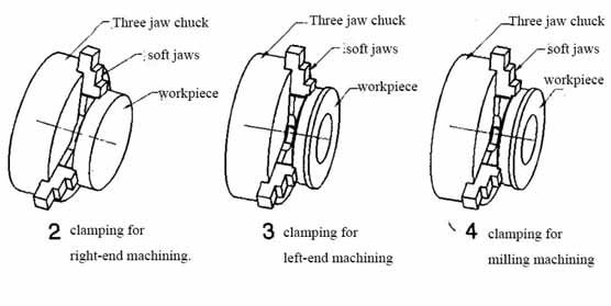
(3) Clamp the outer circle and inner hole using a three-jaw chuck for external turning and inner hole machining on the end face.
(4) Clamp the overall thickness using a three-jaw chuck for external turning to ensure the total thickness.
(5) Punching and milling: Using a three-jaw chuck, perform counter boring, threading, and milling the U-shaped groove.
Fixture Selection
Tool and Cutting Parameter Selection
(1) Outer Circle Tool and Cutting Parameter Selection
The outer circle machining involves rough and finish machining. SANDVIK system tools are chosen for this purpose. Based on the machining requirements, the DCLNL2020M09 tool holder is selected to match the tool post. Diamond-shaped inserts are used. Specifically, the CNMGO90408-PR and CCMTO90404-PF inserts are chosen. The CNMGO90408-PR insert has a slightly larger cutting edge radius, providing higher tool strength and lower cutting edge sharpness, making it suitable for rough machining. On the other hand, the CCMTO90404-PF insert has a smaller cutting edge radius, lower tool strength, and higher cutting edge sharpness, making it ideal for finish machining.
Given the larger size of the outer circle in this component, a rough turning speed of 600 r/min is selected to ensure that the linear velocity remains within reasonable limits. Following the principle of removing excess material as quickly as possible during rough turning, a cutting depth of 2.5 mm and a feed rate of 0.25 mm/r are chosen. For finish turning, to balance surface roughness and efficiency, a speed of 600 r/min, a cutting depth of 2.5 mm, and a feed rate of 0.25 mm/r are selected.
(2) Inner Hole Turning Tool and Cutting Parameter Selection
Generally, when turning inner holes, a pre-drilled hole on the stock material is required. The pre-drilled hole size should be as large as possible, typically aiming for a diameter 3 to 4 mm smaller than the smallest inner hole dimension on the component drawing. However, due to the larger minimum diameter of the inner hole in this component and the limitations of the chosen machine, the maximum drill bit size that can be used is 40 mm. Consequently, the final pre-drilled hole diameter is 40 mm.
Based on the pre-drilled hole diameter, the 20M-SCLCRO6 tool holder is selected, which has a larger diameter and better rigidity.
As the inner hole diameter is smaller compared to the outer circle, the rotation speed can be increased appropriately. Since the cutting conditions for inner hole turning are generally poorer and the rigidity of inner hole tool holders is usually lower than that of outer circle tool holders, the cutting depth for inner hole turning should be smaller than that for outer circle turning. Therefore, for rough inner hole turning, a speed of 1,500 r/min, a cutting depth of 2 mm, and a feed rate of 0.2 mm/r are chosen. For finish inner hole turning, a speed of 1,800 r/min, a cutting depth of 0.3 mm, and a feed rate of 0.1 mm/r are selected.
(3) Tool and Cutting Parameter Selection for Counterbored Holes
The counterbored holes are used for bolt installation with relatively low precision requirements. Therefore, drilling is chosen as the method. Initially, the R840-0500-30-A0A drill bit is selected to drill a 6 mm through-hole. Due to the smaller diameter of the drill bit, referring to the SANDVIK tool manual, a rotation speed of 1,500 r/min, a cutting depth of 6 mm, and a feed rate of 320 mm/min are chosen. Subsequently, the R216.32-15030-AC10P flat-bottom drill is selected to create a 15 mm counterbored hole. This approach saves milling time and enhances processing efficiency. Given the larger diameter of the drill bit, according to the cutting parameter manual, a rotation speed of 800 r/min and a feed rate of 80 mm/min are chosen.
(4) Tool and Cutting Parameter Selection for U-shaped Groove
When machining the U-shaped groove, a tool with the same diameter as the U-shaped groove or a smaller-width tool can be used. The advantage of using a tool with the same diameter as the U-shaped groove is higher efficiency and convenient programming. However, the disadvantage is that the dimensions are determined by the tool and cannot be adjusted through programming. Using a smaller-width tool allows dimensions to be determined by programming, providing adjustability, but at a relatively lower efficiency. Considering the tolerance of the U-shaped groove is 0.1, and to ensure machining accuracy, a 10 mm end mill cannot be used directly. Instead, an end mill smaller than 10 mm is required. To balance tool rigidity and machining efficiency, an 8 mm end mill is chosen with the model R216.32-08030-AC1OP. Referring to the SANDVIK tool manual, a rotation speed of 3,200 r/min, a cutting depth of 2 mm, and a feed rate of 800 mm/min are selected.
(5) Tool and Cutting Parameter Selection for Threaded Holes
For machining an M6 thread, a 5 mm drill bit is used to drill the bottom hole, followed by selecting an M6×1 tap for threading. During threading, it’s important to ensure that feed rate = rotation speed x pitch. Therefore, a rotation speed of 1,000 r/min and a feed rate of 1,000 mm/min are chosen.
Processing Summary
(1) Flexible Application of Three-Jaw Chuck: The three-jaw chuck is a widely used universal fixture that can be employed not only on lathes but also on milling machining centers. It can be used with external jaws to clamp the outer circle or with retractable jaws to clamp the inner hole, ensuring coaxiality across multiple clamping operations.
(2) When machining the U-shaped groove along the circumference of this connecting ring, a tool with a smaller width than the groove is utilized to ensure better accuracy.
Processing Recommendations
Conclusion
The machining of turned and milled parts primarily revolves around the clamping issues on both lathe and milling machines. With the ongoing advancement of CNC technology, the use of milling-turning CNC machines will become increasingly common. When machining turned and milled parts, the integration of turning and milling processes can effectively reduce manual clamping and handling time for components, ultimately enhancing efficiency.
Free Sample
Explore Other Guide and Resource

Swiss Lathe Manufacturers – Top 10 You Need to Know
Discover the top 10 Swiss lathe manufacturers known for their precision and quality. Learn about industry leaders today!

Considerations for CNC machining production
Explore the intricacies of CNC machining production with a focus on hole machining and boring processes. Delve into considerations, safety measures, and practical tips for effective CNC operations. This guide
Passivation of Aluminum and Aluminum Alloys
For aluminum and aluminum alloy workpieces, whether obtained through chemical oxidation or anodization, the resulting oxide film is porous, prone to contamination, and has poor corrosion resistance. Even after coloration