

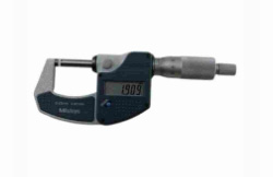
Digital Outside Mierometer
The Outside Micrometer, commonly known as the Spiral Micrometer, is often simply referred to as the "micrometer." It is a highly precise measuring instrument used for measuring the diameter of an object.
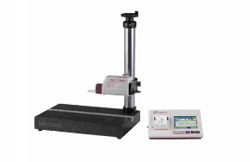
Mitutoyo Roughness Tester
Roller shaft,Turn-milling composite processing, 7075 aluminum machining, and another turning and milling CNC machining parts.
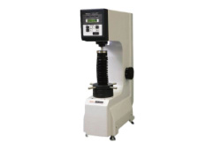
Mitutoyo Hardness Tester
A hardness tester is a specialized tool used to measure the surface hardness of coatings. It has the capability to convert between six different hardness scales, which include HL, HRB, HRC, HB, HV, and HS.
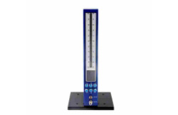
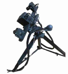
Pneumatic Measuring Instrument
A pneumatic momentum meter is a new type of measurement tool used to convert changes in the dimensions of a workpiece into variations in compressed air flow or pressure, which are then displayed through an indicator.
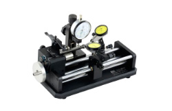
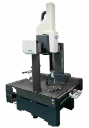
Concentricity Tester
The concentricity tester is primarily used for precision measurements of roundness, concentricity, circular runout, and cross-section variations of shaft components. It provides high accuracy, with measurements reaching up to 0.005mm, allowing for precise and reliable results.
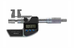
Digital Inside Mierometer
INSIDE MICROMETER, as known a mechanical instrument used for precise measurement of internal dimensions. It can read up to the third decimal point (thousandth). This extreme level of precision is why it is called the "micrometer."
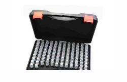
Pin Gauges
The pin plug gauge measures the inner diameter of a round hole. It is primarily utilized for measuring the inner diameter of small round holes that range between 0-10mm and requires a high level of precision.
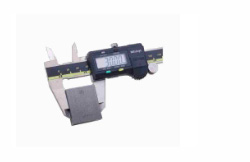
Digital Caliper
A digital caliper consists of a main ruler and a vernier. It is used to measure length, inside and outside diameter, and depth. The resolution for digital calipers is 0.01mm. It allows an error of ±0.03mm/150mm.
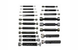
Thread Ring Gagues
The purpose of a thread ring gauge is to verify the accuracy of the external thread's dimensions. The specifications of thread ring gauges are categorized into three types: coarse teeth, fine teeth, and pipe thread.
Thread Plug Gagues
The thread plug gauge is a measuring tool that is used to determine the precision of the internal thread's size. This gauge can be categorized into three types: ordinary coarse teeth, fine teeth, and pipe thread.
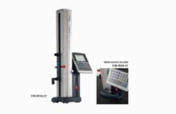
Mitutoyo Digital Height Micrometer
The pin plug gauge measures the inner diameter of a round hole. It is primarily utilized for measuring the inner diameter of small round holes that range between 0-10mm and requires a high level of precision.
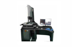
Project Meter
A digital caliper consists of a main ruler and a vernier. It is used to measure length, inside and outside diameter, and depth. The resolution for digital calipers is 0.01mm. It allows an error of ±0.03mm/150mm.