Considerations for CNC machining production
Considerations for CNC Machining Production
Safety in CNC machining production.
CNC Machining Knowledge
1. When machining the side of a workpiece with a fixture, check the gap between the workpiece and the fixture if the Y-axis is asymmetrically divided.
2. Plastic multi-surface CNC machining with a tolerance of 0.05mm requires screw-locking machining.
3. Thickness confirmation of double-sided adhesive: Take the adhesive amount of two layers, subtract the amount of adhesive between two layers of paper, and divide the difference by 2 to get the single adhesive thickness.
4. When using hot melt adhesive, pay attention to: 1) Softening of the adhesive at high temperatures. 2) Oil dripping from the machine tool, and oil infiltration on the circuit board. 3) Insufficient temperature of the adhesive leads to poor extrusion and inferior results.
5. When machining the reverse side of a workpiece, the reference angle (inclined angle) is generally in the lower right corner (symmetrical to the front face along the y-axis), and the reference edge of the workpiece should be polished well.
6. If there is water mist while blowing air with an air gun, go to the air compressor to drain the water. The large air storage tank should also be drained daily.
7. There is a small water tank at the back of the machine tool. If there is excessive water vapor in the machine tool tank, clean it at the back of the machine tool.
8. For vertical tool magazines on machine tools, tighten the screws on the top until the red light comes on.
9. The tool library in the machine tool should be organized. In the TOOL column, the value represents the number of tools in the library, and the main spindle tool should not be duplicated.
10. When operating a drilling or milling machine, be careful not to let gloves and hair get caught in the machine.
Hole Machining Knowledge
1. Generally, the diameter of the center drilling point is larger than the aperture by 0.2mm. The larger the diameter of the center drill, the larger its transverse blade.
2. Some center drills need to avoid the bottom due to length or strength issues.
3. The angle of most center drills is 90 degrees, and the length affects the reversed angle. Prolonged use can also cause a larger roundness deviation at the tip due to wear.
4. Some base plates have more waste holes, so a center drill is used to locate the positions.
5. If the hole requires higher accuracy, use a small drill bit for initial drilling and then use a standard drill bit.
6. Pay attention to chip removal by blowing air or lubrication. Insufficient chip removal may result in fusion.
7. Sometimes a 5.9mm drill bit is used for positioning holes.
8. After the drill bit is worn, the tapered hole it drills has a larger diameter at the top and a smaller diameter at the bottom. It is necessary to use a measuring tool to check the hole.
9. Common drilling cycle commands include G98 G83X, Y, Z, Q, R, F. Q represents the drilling depth. The smaller the drill bit, the smaller the Q value, the higher the drilling speed, and the smaller the feed rate (too low feed rate can cause the hole to enlarge).
10. Center drilling is used to check the dimensional accuracy of the hole positions.
11. Center drills combined with offset drills will definitely produce off-center holes.
12. After completion, check the hole diameter and relative dimensions to ensure correctness before proceeding to the second piece.
Tapping
1. The size of the bottom hole is generally the major diameter minus the pitch diameter. For example, for an M4*0.7 tap, the bottom hole would be 4 – 0.7 = 3.3mm.
2. Adjust the size of the bottom hole according to the material. For difficult-to-tap materials, increase the size by 0.05mm. For easy-to-tap materials, use the standard hole size. For soft materials, decrease the size by 0.05mm.
3. Use a pin gauge to inspect the bottom hole to ensure consistency and prevent tapered or off-center holes.
4. Remove any impurities from the bottom of the hole and apply oil to lubricate it.
5. After confirming the length of the tap, tighten it and perform axial adjustment (tap depth should be less than drill depth by 0.5mm).
6. Common cycle commands used are G98 G84X, Y, Z, Q, R, F. Here, Q represents the drilling depth. The smaller the tap, the smaller the Q value, resulting in higher drilling speed. The feed is based on the pitch. For example, for an M3 tap in aluminum with a 2.55mm bottom hole, the command would be M3S1000 G98G84X100.Y10.Z-10.Q3.R1.F0.5.
7. After the first empty cycle, use a gauge to check the number of rotations and tap depth, as well as the correctness of the chamfer.
8. Because the hole needs to be clean, sandblasting is prohibited in the hole during post-treatment.
Milling Holes
1. Pre-drill with a residual margin of about 0.3mm on one side, then performs milling.
2. Please ensure that the side cutting edge of the tool is free from damage and ensure that both the length of the tool and the length of the blade are suitable for machining the workpiece.
3. Adjust the tool offset, ensure no debris inside the hole, and lubricate during the process.
4. Pay attention to the sound of the tool rubbing against the hole wall during milling. If there is any, lift the tool slightly to avoid a collision.
5. Use G41D1 for tool radius compensation (offset with negative value).
Reaming Holes
1. Confirm the depth of the bottom hole, with a diameter allowance of 0.1-0.15mm, and clamp the workpiece securely.
2. Clean the hole thoroughly and apply lubrication.
3. Verify the reamer’s specifications, smoothness, and test the program using scrap materials.
4. Inspect the hole dimensions with a pin gauge or an internal micrometer, and visually check the smoothness.
5. Perform the reaming process, checking the smoothness of the dimensions.
6. After completion, protect the hole, avoiding applying putty or causing scratches.
7. Reaming speed is generally 800, with a feed rate of 60. Use command G85XYZRF (lift tool for return milling) or G88XYZPRF (bottom stop).
Boring Holes
1. Confirm the depth of the bottom hole, with a diameter allowance of 0.5-1mm, and clamp the workpiece securely.
2. Install the boring tool (confirm the size and type of cutting inserts) and ensure proper clamping (type of tool head and clamping).
3. Perform trial cutting, adjustments, and observe the smoothness.
4. Ensure consistent margins on both sides of the tool to guarantee dimensional accuracy.
5. Measure the diameter of the workpiece hole and other dimensions, such as tapered holes, using a micrometer.
6. Boring speed is generally 800, with a feed rate of 60. Use command G85XYZRF (lift tool for return milling) or G88XYZPRF (bottom stop).
About Boring Holes
What is boring hole machining?
Compared to other machining processes, boring is considered more challenging. It relies on adjusting a single cutting tool to achieve micro-level hole dimensions, such as H7, H6.
Characteristics of center-based boring hole machining
Tool rotation
Additionally, during center-based boring, the direction of chip flow constantly changes, making tool tip cooling, workpiece cooling, and chip evacuation more challenging compared to lathe machining. In particular, the problem of chip evacuation during the rough boring of blind holes in steel using vertical center-based machining has not been fully resolved.
Spring-back (chatter)
The rigidity of the tool system: This includes the rigidity of the tool holder, boring bar, boring head, and intermediate connecting parts. As it is a cantilevered operation, the rigidity of the tooling system is particularly important for small holes, deep holes, and the machining of hard materials.
Dynamic balance of the tool system: If the tool itself has an unbalanced mass relative to the axis of rotation of the tool system, the imbalance of centrifugal force during rotation can cause vibration. The dynamic balance of the tool, especially during high-speed machining, has a significant impact.
Workpiece characteristics or the rigidity of the workpiece fixation: Some small or thin parts may lack sufficient rigidity or cannot be adequately fixed due to the shape of the workpiece.
Tool tip shape(Geometry of Tool Edge): The cutting resistance varies depending on the shape of the tool tip’s leading edge, clearance angle, tip radius, and chip breaker groove shape.
Points to note in boring hole machining:
1 Select a suitable boring tool to enable fine adjustment of the boring process, minimize center offset, and allow for high-speed cutting.
2 Choose cutting inserts with appropriate cutting performance (precision grade).
3 Coordinate the cutting speed to achieve effective boring operations (refer to the chart).
PS:
1.When using the MC machine for boring, pay attention to the spindle positioning direction.
2.If chattering occurs during boring, it may indicate a spindle imbalance. In such cases, reduce the rotational speed or use an adjustable balance boring head like NBJ16S.
3.If the bore diameter is too rough, decrease the feed rate and increase the rotational speed.
4.If the bore diameter exhibits a slight slope, check if the reserved boring allowance is excessive or insufficient. Insufficient allowance leads to tool wear, and the feed rate should not be too low.
5.The maximum rotation speed of this boring tool is 1600 rpm, but the speed may need to be reduced due to center offset and machine conditions.
Classification of Plastics
Engineering Plastics
ABS: Commonly available in natural color (milky white), transparent, and black. It emits a burnt smell when cut.
PC: Most commonly transparent, but also available in black. Harder than ABS, higher melting point, odorless when cut, and less prone to sawdust sticking.
POM: Most commonly white. It has a smooth texture, produces powdery sawdust, is prone to deformation, and generally does not bond well with adhesives.
PP: Most commonly water-white in color. It has good toughness but not as hard as PC. Odorless when cut and prone to deformation.
PMMA (Acrylic): Commonly transparent or black. It is brittle, has a smooth texture, sawdust has a bitter taste, and forms granular particles.
Nylon Plastics
PA66: White in color, with a yellowish hue on the surface. It is hard, has strong toughness, a high melting point, and is not easily prone to tool sticking.
PA46: Deep yellow, with a light brown surface.
PA66+GF30: Black. Compared to PA66, it contains 30% glass fiber reinforcement.
PA66+GF50: Black. It has a higher glass fiber content than PA66+GF30, resulting in a harder and more brittle material, with a crisper sound when cut.
Materials that are not frequently processed
PDF milky white
PPS beige
PET white adhesive
PA (similar to domestic nylon)
Front side
1. Receive the process sheet and confirm the existence of the process, the type of material, size, thickness, quantity to be made, and the tool to be used.
2. The operator strictly follows the type of tool specified in the process sheet and obtains the correct tool with the appropriate diameter and blade length! (Pay attention to the selection of tool cylinder according to the process sheet for clamping)
3. The team leader verifies the material size, thickness, and quantity of the material (do not cut the material privately). The program sheet has already left allowances for length and width, and the thickness is the height of the workpiece.
4. Cut the material evenly on both sides (let the material be naturally placed without applying excessive external force), leaving a 2mm allowance to ensure a smooth and spotless surface. Check the flatness on a granite platform (the deflection should be less than 0.03mm).
5. First, drill a 4.8mm through the hole in the workpiece, and then drill an 8mm counterbore (the material is tough and hard, and the hole should be drilled firmly). Finish the opposite side flat (pay attention to smooth and even bottom surfaces).
6. Drill screw holes: For aluminum plates, drill a 2mm deep center hole (first drill 0.2mm to locate the hole position), and then drill a 3.4mm deep hole with a tap (the tap should go in 12mm deep).
7. Lock the plate: Confirm that the aluminum plate is flat and smooth. The workpiece should have no burrs, and the screws should not be loose or too tight. After locking, apply adhesive to the four sides.
8. Surface finish: Cut off the excess material left on the front side.
9. Positioning hole: First drill a hole, and then use a smooth positioning pin to check if it fits tightly. If it is not tight, use a 5.9mm drill to drill the positioning hole (center drill).
10. Rough machining: Confirm that the tool is in good condition and correct. Check the tool setting, and the tool deflection should be less than 3 lines. (Observe whether the material of GF30/GF50 is crumbling)
11. Finish machining: Confirm that the tool… The tool deflection should be less than 3 lines. (Observe the workpiece)
The side cutting edge of the tool should be long and sharp enough. If it is not enough, raise the tool slightly and then lower it.
12. T-slot machining: Test the tool * Test the cutting edge’s thickness, diameter, and smoothness. (For some workpieces, apply putty on the surface before cutting the T-slot)
Check the swing of the tool edge * Do not check the tool holder, as the edge and the holder may not be concentric.
The tool thickness may not be accurate, and the caliper measurement may not be accurate, because the edge heights may be different.
Method for testing the tool thickness: Take a nylon strip with a flat surface, align the top against the tool, lower it by 10mm, and then pull it horizontally by 2mm on the side of the material. Measure it.
13. Slot Machining: Pay attention to blowing air to clear debris. When checking the slot with a needle gauge, it should slide naturally to the bottom.
14. Hole Machining: Ensure that the punch rod does not rub against the hole wall, the side blade is in good condition, and use a needle gauge to slide to the bottom for adjustment. (The wall should be smooth.)
15. Counterbore: Raise the center drill by 2mm for machining, then lower it for adjustment (use a ball probe with strict requirements).
16. Front Finish: Check the surface flatness, making sure it is less than 4 units. Inspect critical dimensions according to the drawing, and check the appearance.
Backside
1. Remove burrs: Use sandpaper to remove burrs, avoiding using hard objects that may scratch the workpiece.
2. Apply stone paste: Do not use expired stone paste as it may become too soft on the outside while still wet on the inside. After applying, immediately scrape it flat. It becomes harder to scrape when dry.
3. Clean the locating holes and screw holes from any stone paste.
4. Drill locating holes on the aluminum plate, following the same procedure as step 8 on the front side.
5. Secure the screws after positioning, following the same procedure as step 6 on the front side.
6. Check the workpiece for surface flatness. If there is a difference of more than 4 units, remove the workpiece and check if there is anything protruding on the bottom.
7. Take height measurements according to the program sheet. (Check if the reference rod is a standard 10.0mm. If it measures 9.98mm, raise it by 2 units.)
8. Finish the surface to the thickness indicated on the program sheet.
9. Start machining (same as steps 9-15 on the front side).
10. Cut off the workpiece, confirming the surface flatness and correct cutting.
11. After removal, place the workpiece in the designated location.
12. Perform a full inspection and confirm the correctness of the first piece.
Side Surface
1. Refer to the program sheet to understand the machining method.
2. Calibrate the fixture and tighten it securely.
3. After placing the workpiece in the fixture, confirm that it fits tightly without looseness or gaps.
4. Clamp the workpiece, being careful not to move the fixture.
5. Check that the workpiece is flat (each plate’s thickness may vary, so pay attention to the middle section as well).
6. Ensure there are no burrs in the middle section and pay attention to the measurements when using the probe.
7. Test the probe and check if the workpiece is in the correct position.
8. Perform machining (same as steps 9-14 on the front side).
9. Repeat the process for the second piece (refer to step 7).
10. Please conduct a comprehensive inspection of the first piece to ensure its accuracy.
Note: GF50 has a crisp sound, while GF30 has a dull sound. Both materials are prone to surface breakage, so extra attention is required.
Reference for CNC engraving machine operation process.
Power-on Preparation
1. Check the voltage: 380 volts.
2. Check the network cable connection is normal.
3. Ensure there is sufficient lubricating oil and cutting fluid for the guide rails and coolant.
4. Ensure there are no foreign objects on the workbench and inside the machine tool.
Power-on Inspection
1. Check for any electrical leakage phenomenon in the machine tool.
2. Verify the normal operation of the spindle cooling system: In MDI mode, enter “M3S4500” in the PROG column; when the spindle rotates, the cooling machine at the rear of the machine tool should start.
3. Restore deleted offsets: In MPG mode, check the coordinates in the OFFSET column and restore the offsets.
Machining Precautions
1. Confirm that the workpiece is leveled, straightened, and securely clamped.
2. Perform tool offset twice to ensure correct tool centering: In MPG mode, select the G54 coordinate system by pressing the left and right direction keys, and enter the touch points as X1, X2, Y1, and Y2. Repeat the same process for G55 coordinate system and verify.
3. Ensure correct tool data input: Touch the 12-tool probe against the machined surface, keeping it at zero height. In MDI mode, enter “G36” to activate the automatic tool length measurement. For each workpiece, the first step must be performed after following the previous steps. After mounting each tool, execute “M6T1.”
4. Ensure the correct program is loaded: The program should contain “G43H1Z10.”
5. Activate manual DRN (DRN key/special function for engraving machine) and pay attention to residual values.
Collision Issues
Incorrect tool offset input is the most common cause of collisions.
1. Coordinate offset input error.
2. Workpiece coordinates input error (G54, G55, etc.).
3. Length compensation input error or incorrect call for G43.
4. Radius compensation input error or incorrect call for G41.
5. Input error for G40, G49, or G80.
Operating errors
1. Selecting the wrong program.
2. Incorrect tool installation.
3. Mistakes in setting the machining coordinates.
4. Failure to return to the home position after powering on.
5. Errors in using handwheels or manual directions.
Special programs can also cause collisions.
1. Multiple tool changes within the program (collision due to tool offset errors).
2. The program starts with the tool down at the machine reference point (collision with the pressure plate or screw).
3. The program starts with a diagonal tool movement (Z appears before H).
4. Low safety clearance height (collision with the pressure plate or nut).
Rare occurrences
1. Displacement of handwheel, malfunction, or short circuit of machine tool buttons.
2. Machine tool M-codes not executed properly:
(For example, in machine A, M6 must be executed at G91G30Z0 point; in machine B, M6 must be on the same line as T and M7 must be off).
3. Tool dropping.
4. When loading the program, data overflow or programming error can lead to collisions.
5. The program was not properly handled, and there are errors in the tool change program
Machine tool defects
1. Automatic tool measurement (M6T1) or automatic tool length detection (G36) is performed while the Z-axis is locked.
2. The spindle on the engraving machine can rotate but may not tighten the tool properly.
3. The default initial speed of the engraving machine spindle is too high, which can easily damage the tool centering pin.
Free Sample
Explore Other Guide and resource
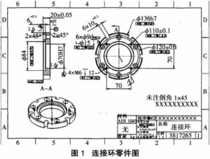
Analysis of CNC turned and milled parts
The CNC machining process arrangement of the combined turning and milling parts involves considering the processing sequence and clamping scheme to ensure the machining accuracy and dimensional tolerance of the
12 Automatic Lathe Manufacturers in china in 2024
The CNC machining process arrangement of the combined turning and milling parts involves considering the processing sequence and clamping scheme to ensure the machining accuracy and dimensional tolerance of the

CNC Turning Services 101 – Know the Every Unknown
Get a detailed overview of CNC turning services. Explore the benefits, types, and materials involved in creating high-precision parts for various industries.
